
Hahn & Sohn ATS Switch 125A
Hahn & Sohn ATS Switch 125A is an automatic transfer switch designed to switch the power supply between the utility grid and a backup generator system. In the event of a power outage or unacceptable mains parameters, it sends a signal to start the generator and, once the correct voltage is reached, automatically transfers the load power supply to the generator.
Once the utility power supply is restored, it switches the load back to the main power source and stops the generator after the set delay. The device is designed for a three-phase 230/400 V network, with a rated current of 125 A and a control voltage of 24 V DC.


The ATS switch is designed to automatically ensure the power supply of a building or technology in the event of a mains power failure. Two power sources are connected to the switchboard – the main utility power supply and the backup power supply from the generator – while the output leads to the powered load.
- During normal operation, the load is powered from the utility grid. The control unit continuously monitors both power sources and evaluates their status. It monitors overvoltage, undervoltage, overfrequency, underfrequency and phase failure.
- Once a stable utility power supply has been restored, the ATS transfers the load back to the utility grid. The generator then remains in operation for the set period of time and subsequently receives a stop signal. This process reduces the need for manual operation and enables automatic restoration of power, for example in facilities, technological systems, pumps, warehouses or other buildings where the availability of electrical power is important.
- This particular version has a rated voltage of 230/400 V, a rated current capacity of 125 A and a control voltage of 24 V DC. The internal transfer switch is wired for three phases and a neutral conductor, i.e. A, B, C and N. Separate terminals are provided for the utility input, generator input and output to the powered load.
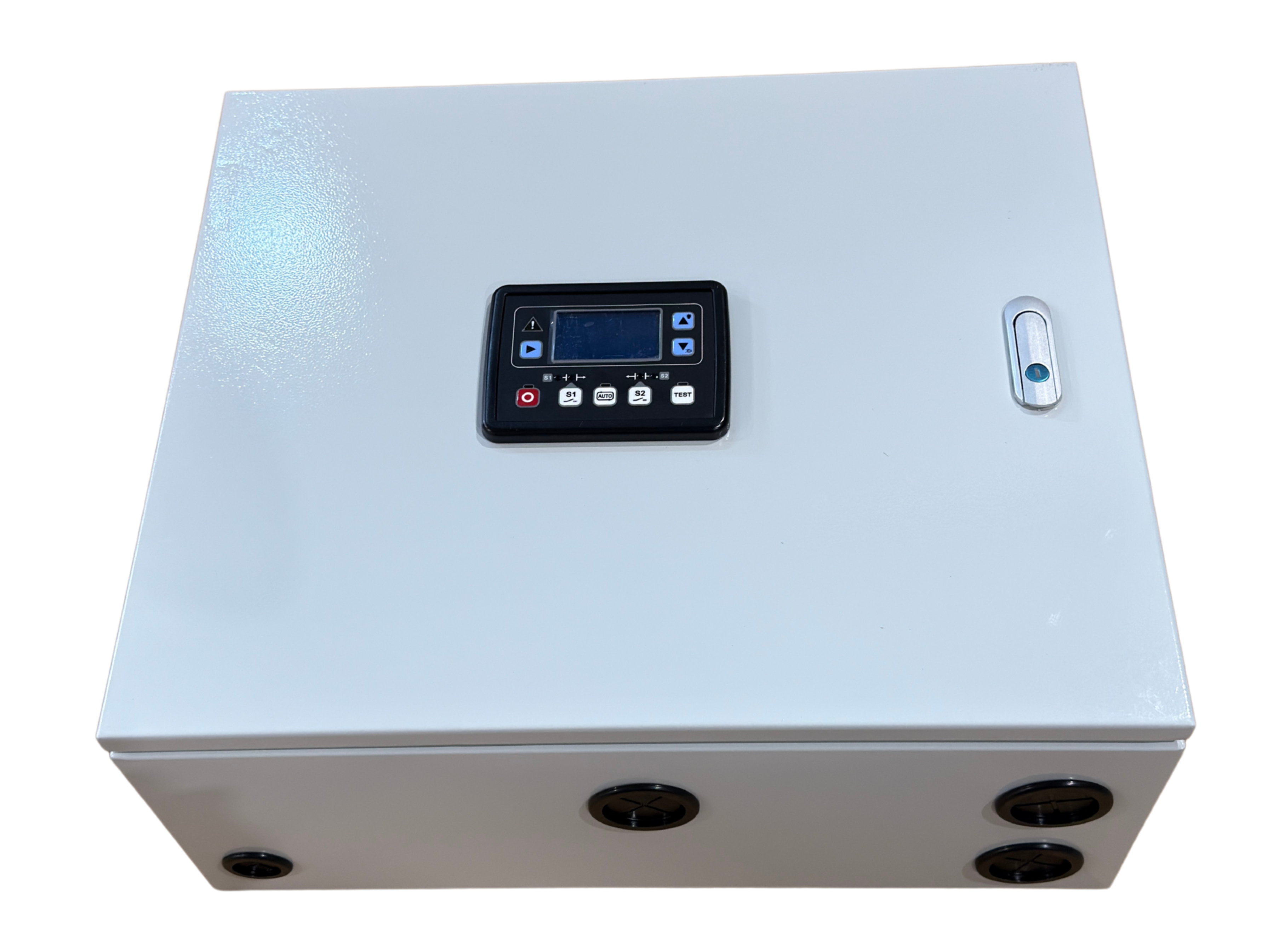
- A digital control panel is located on the cabinet door, allowing selection of automatic and manual modes, testing and monitoring of operating conditions. Inside the cabinet are the transfer mechanism, control electronics, terminal blocks, relays, fuse elements, battery charger and grounding point.
- The integrated mains charger helps keep the generator's starting battery charged while utility power is available. Once fully charged, it can switch to maintenance charging mode.
- The switchboard is housed in an enclosed metal cabinet with a lockable door, perimeter seal and prepared cable glands. The cabinet protects the internal electrical components while also restricting access by unauthorized persons.
WHY CUSTOMERS CHOOSE IT
- Automatic switching between the utility grid and generator
- Rated current of 125 A for higher-power three-phase installations
- Automatic starting and stopping of a compatible generator
- Voltage, frequency and phase failure monitoring
- Option of automatic and manual operating modes
- Integrated charging of the generator starting battery
PRACTICAL TIP
The ATS switch must be correctly matched to the generator output, building protection system, cable cross-sections and starting system voltage. Before ordering and installation, we recommend checking in particular the 125 A rated current, 24 V DC control voltage and the generator's remote starting method.
KEY FEATURES
- Automatic transfer switch for two power sources
- Main source: utility grid
- Backup source: generator system
- One common output for the powered load
- Rated current 125 A
- Operating voltage 230/400 V
- Control voltage 24 V DC
- Three-phase four-wire connection A, B, C, N
- Automatic and manual operating modes
- Signal for automatic generator start and stop
- Overvoltage and undervoltage monitoring
- Overfrequency and underfrequency monitoring
- Phase failure monitoring
- Adjustable time delays
- Integrated generator battery charger
- Digital control panel
- Transfer mechanism with electrical and mechanical interlocking
- Lockable metal cabinet
- Grounding point and prepared cable glands
USE / INSTALLATION / OPERATION
Suitable applications
The ATS switch is suitable, for example, for:
- backup power supply for manufacturing and commercial facilities,
- workshops and service facilities,
- warehouses and agricultural facilities,
- pumping and technological systems,
- office and commercial premises,
- residential and apartment buildings with suitable electrical installations,
- other facilities using a compatible generator with automatic starting.
Automatic operation principle
- The ATS monitors the voltage of the utility grid and generator.
- In the event of a mains failure, it sends a signal to start the generator.
- Once the correct operating parameters are reached, it transfers the load to the generator.
- Once utility power is restored, it transfers the load back to the main power supply.
- After the set delay, it sends a signal to stop the generator.
- The generator remains ready in standby mode.
Manual mode
The device also allows manual switching between the main and backup power sources. Before manual switching, it is necessary to:
- disconnect the powered load,
- switch off both the utility power source and the generator,
- set the control unit and transfer switch to manual mode,
- only then change the position of the transfer switch.
Manual switching while the load is connected is prohibited. The transfer mechanism must also not be operated manually when it is set to AUTO mode.
Installation
- Connect the utility supply to the main source terminals.
- Connect the generator output to the backup source terminals.
- Connect the ATS output to the powered load.
- Connect the control cable for starting and stopping the generator.
- Connect the wires for charging the starting battery.
- Connect the protective conductor to the grounding point.
- After completing the installation, verify the phase sequence and correct operation of both power sources.
- Perform an operational test simulating a mains failure and restoration.
Installation, configuration and servicing must be carried out exclusively by a qualified electrician or authorized service technician. Dangerous mains voltage is present inside the cabinet.
Additional parameters
| Category: | Accessories for power generators |
|---|---|
| Warranty: | 2 years |
| Weight: | 23.85 kg |
| Product: | Automatic Transfer Switch (ATS) |
| Rated voltage: | 230/400 V |
| Rated current: | 125 A |
| Control voltage: | 24 V DC |
| Wiring: | three-phase, 4-wire |
| Wires: | A, B, C, N |
| Number of power supplies: | 2 |
| Source 1: | electricity grid |
| Source 2: | power generation system |
| Number of outputs: | 1 output to the load |
| Operating modes: | automatic and manual |
| Default priority source: | electricity grid |
| Automatic start-up of the generator: | yes |
| Automatic generator shutdown: | yes |
| Surge protection: | yes |
| Undervoltage check: | yes |
| Excessive frequency control: | yes |
| Check for insufficient frequency: | yes |
| Phase failure detection: | yes |
| Checking the phase sequence: | The control unit’s function is adjustable |
| Cabinet design: | metal, lockable |

Product rating
Be the first who will post an article to this item!
Discussion
Be the first who will post an article to this item!
